
Description
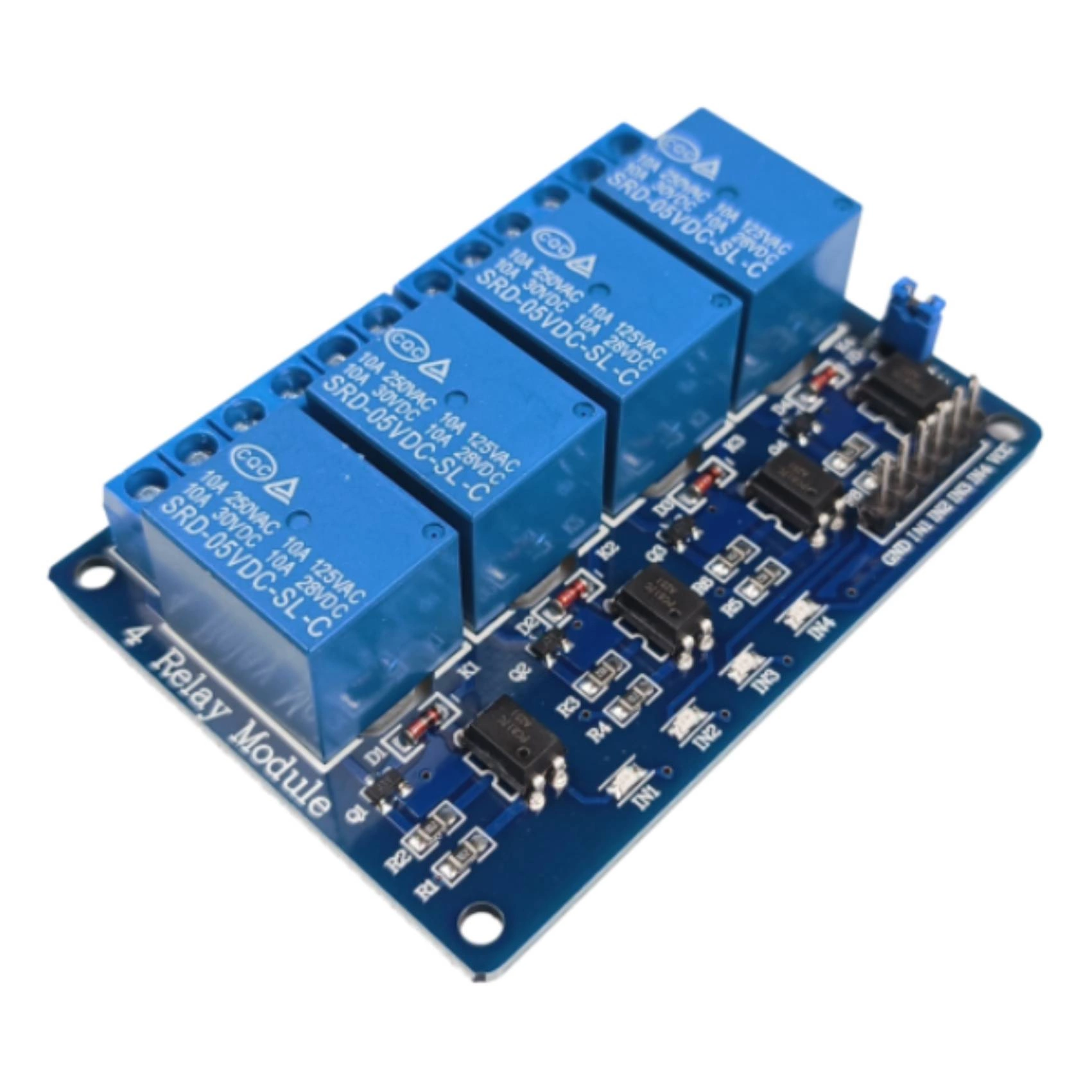
5V to 10A/250V relay module – with optoisolation for Arduino – 4 channels
Universal 5V relay module with optoelectronic isolation for 10A/250VAC.
- The circuit allows you to control the actuators using the ports of the microcontroller or any runner kit.
- The module is supplied with 5V to the corresponding VCC and GND pins.
- Thanks to the use of opto-isolation, the current consumption of the channel is minimal, so you can easily control the microcontroller.
- The operating status LED of each relay channel indicates that the relay is switched on.
- The module is switched on by applying a low LOW state, and therefore ground to the signal inputs In1, In2…
- After removing the jumper, the module enters the test mode, this is a mode in which after the signal is given, the relay does not turn on, only the status LED informs about its operation (this is a useful feature during testing in order not to switch on and off the frequently connected circuit under the relay).
Product features
- Module equipped with four SRD-05 relays with coil powered by 5 V with optical input isolation.
- The module allows you to control four actuators drawing up to 10 amps each using the ports of a microcontroller or any Arduino development kit
- Opto-isolation separates the control signal from the relay power supply part, thus ensuring the safety of the control system operation.
- Application for contact boards, runtime modules, arduino, etc.
- For proper operation, all you need to do is connect the relay power supply and the digital control signal.
- Application examples:
- Lighting controller
- Controller of executive systems
- Switch for electrical equipment including motors
- The module has:
- power LED indication
- lED indication of relay status
- Activation of the relay with the LOW state
Technical data
- Two channels of operation
- VCC supply voltage: 5 V
- IN input voltage: from 3.0 V to 5.5 V
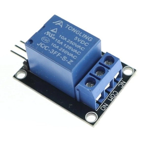
- Relay SRD-05VDC-SL-C (documentation) – 4 pieces
- Coil voltage: 5 V
- Maximum contact voltage: 250 VAC
- Maximum current: 10 A
- Plate dimensions 48x27x20 mm
Connecting
- The module has six input leads VCC, GND, IN- and IN+.
- In order for the circuit to work properly, it is necessary to connect:
- 5 V power supply to VCC pin
- ground to GND
- input signals to IN1 to IN4.
- Thanks to the use of optical isolation, the input voltage can take a value from 3 V to 5.5 V.
- The jumper allows you to select the state with which the relay will be switched on:
- Jumper between VCC and JD – relay on (default setting)
- No jumper between VCC and JD – channel operation test (relay is not switched on, only signal diode)
Video presentation
Guide – relays with Arduino

Reviews
There are no reviews yet.